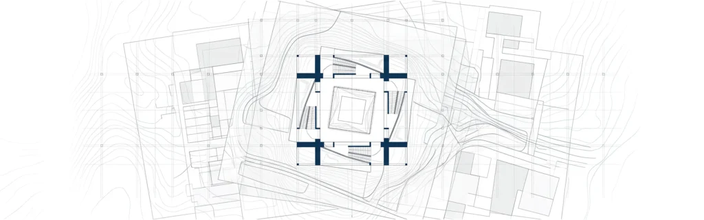

Architectural drawing details are essential for turning design into real construction. They help architects, designers, and project teams communicate how every element of a building should be built. From floor plans to section drawings, these details ensure accuracy, compliance with building codes, and smooth execution on the construction site.
What are the key components of architectural drawings
Architectural drawing details are essential for turning architectural design into a real building. These drawings define how various elements come together, ensuring the construction project runs smoothly.
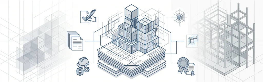
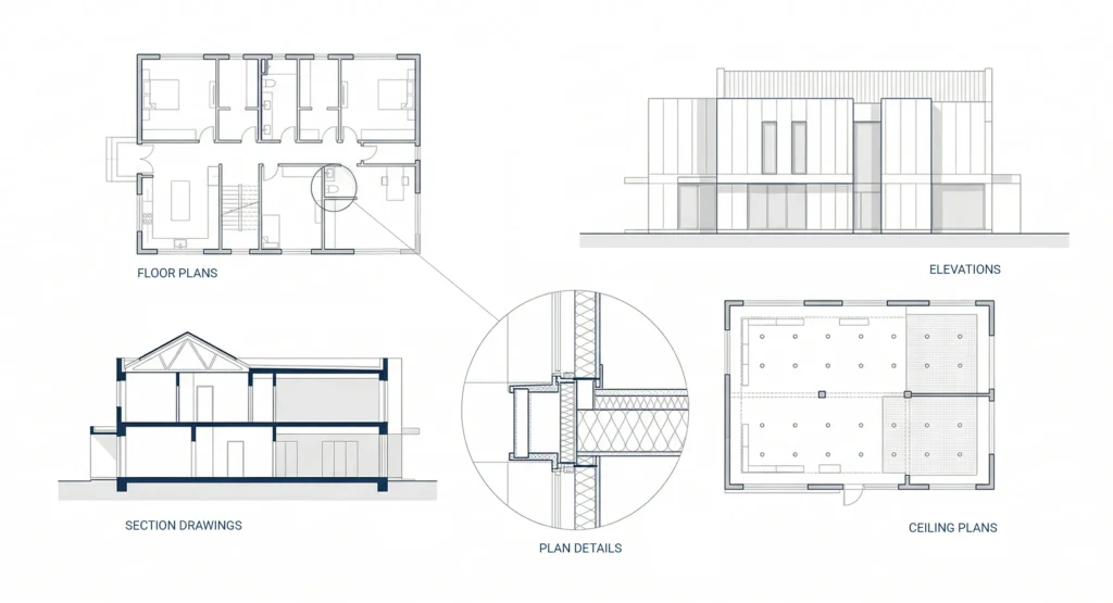
A complete drawing set includes multiple drawing types such as floor plans, elevations, section drawings, and interior elevations. Together, these architectural drawings communicate design intent, spatial relationships, and construction elements clearly.
Key components include:
- Floor plans showing spatial organization of each room
- Elevations describing exterior and interior walls
- Section drawings and cross sections explaining vertical connections
- Plan details that zoom into specific construction details
- Reflected ceiling plans showing lighting and light fixtures
Each of these drawings contributes to a better understanding of how the building will function in real life.
How to read architectural drawing symbols
Understanding architectural drawing details requires knowing symbols used in technical drawings. These symbols represent materials, dimensions, and construction elements.
For example:
- Door swings and window openings indicate movement and access
- Wall thickness defines structural details and materials
- Symbols for furniture, lighting, and fixtures help define space usage
Architects use consistent notation systems to help project teams quickly understand drawings on a construction site. This improves communication and reduces errors during construction.
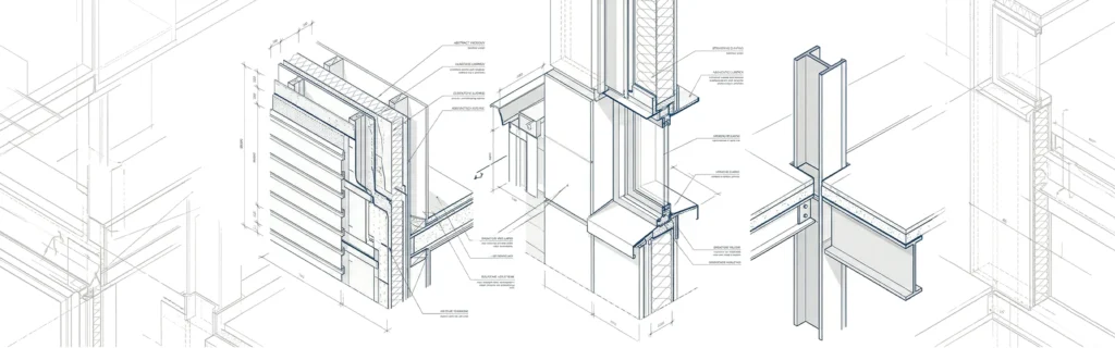
What is the purpose of a wall section detail
A wall section detail is one of the most important architectural drawing details. It shows how the building envelope is constructed, including insulation, structure, and finishes.
These detailed drawings help explain:
- Materials used in exterior and interior walls
- Structural details and support systems
- Connections between floors, walls, and roof
Wall section drawings are usually created at a larger scale to provide further details that cannot be shown in general architectural plans.
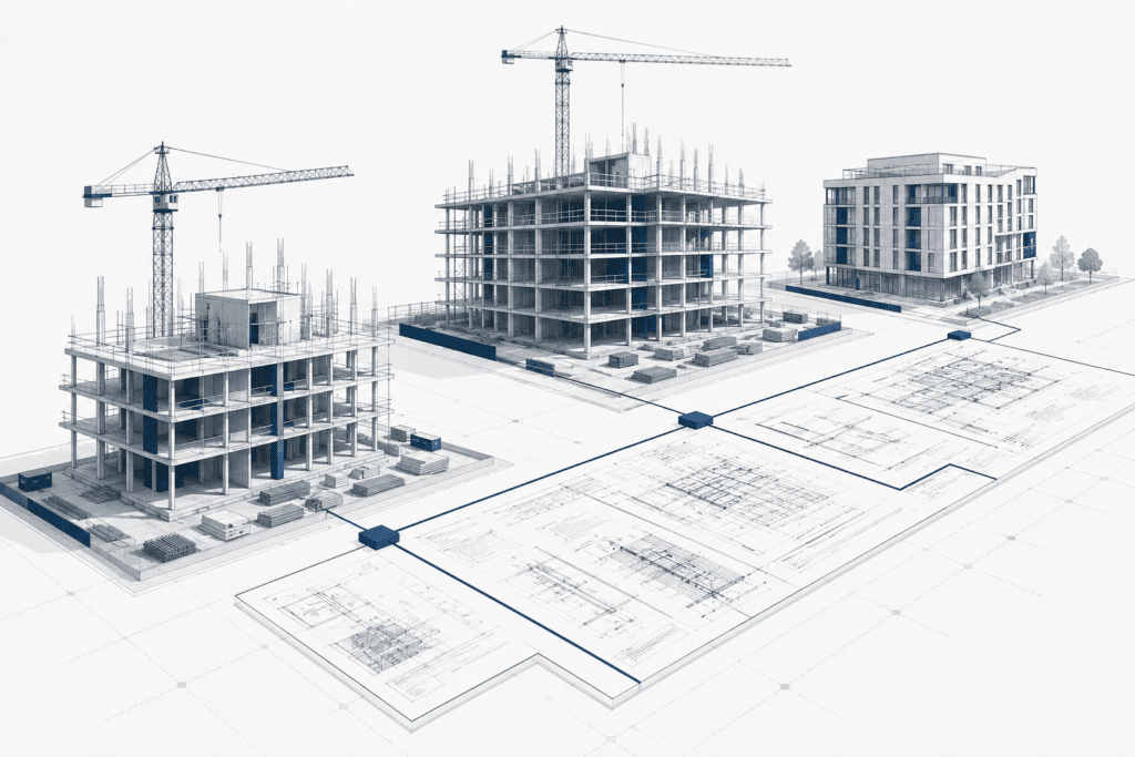
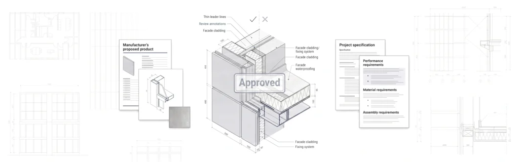
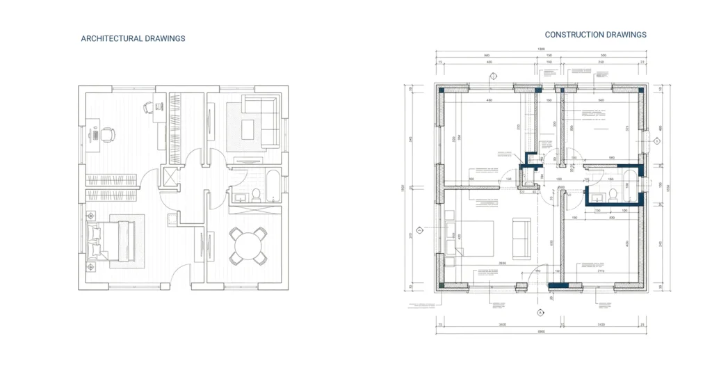
Construction drawings vs architectural drawings differences
Architectural drawings focus on design and layout, while construction drawings provide detailed construction drawings required to build the project.
- Architectural drawings show design intent and spatial relationships
- Construction drawings include construction details, dimensions, and notes
Both are part of the same drawing set and are essential for delivering optimal results in any construction project.
Teams often integrate both into structured documentation workflows supported by architectural construction documentation services to maintain clarity and coordination across the project.
Examples of residential window installation details
Window details are critical in architectural drawing details because they impact performance and durability.
Typical window installation details include:
- Window jamb connections
- Flashing and sealing methods
- Integration with the building envelope
These details ensure windows perform well under real life conditions and meet building codes. In custom home projects, correct window detailing prevents water intrusion and improves energy efficiency.
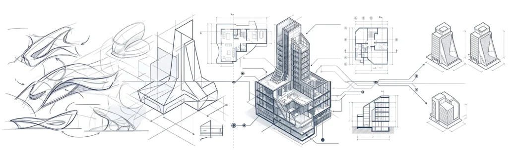
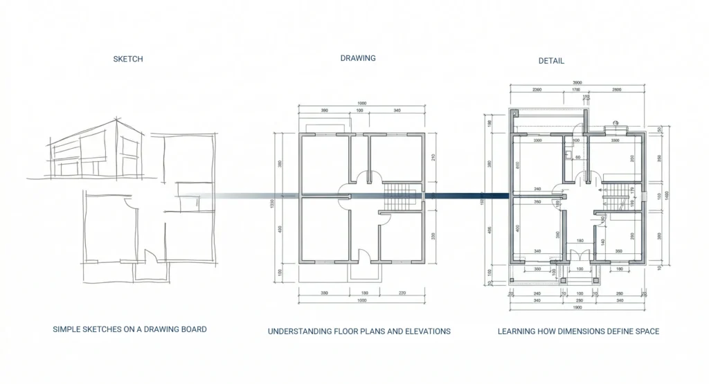
Architectural drawing basics for beginners
For beginners, architectural drawing details can seem complex, but the basics are straightforward.
Start with:
- Simple sketches on a drawing board
- Understanding floor plans and elevations
- Learning how dimensions define space and structure
Over time, beginners move from two dimensional sketches to more detailed drawings that include materials, construction elements, and spatial relationships.
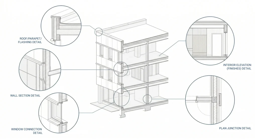
Common types of architectural detail drawings
Architectural detail drawing types vary depending on the stage of the design process.
Common types include:
- Wall section drawings
- Window and door details
- Roof and flashing details
- Interior elevations for room finishes
- Plan details for construction elements
Each type helps architects and designers communicate specific aspects of the building clearly.
For a broader understanding of how these fit into the full workflow, see architectural design and drawing.
Best software for creating architectural details
Modern architectural drawing details rely on design software and CAD tools.
Popular options include:
- AutoCAD for precise technical drawings
- BIM tools for 3D modeling and coordination
- Rendering software for visualizations
These tools allow architects to create accurate drawings, manage dimensions, and coordinate large construction projects efficiently.
Most professionals rely on architectural CAD drawing systems to streamline the drawing process and improve consistency.
Standard scales for architectural detail drawings
Architectural drawing details are typically created at a larger scale than general drawings to show precise information.
Common scales include:
- 1:20 for construction details
- 1:10 for more complex junctions
- 1:5 for highly detailed elements
Using the right scale ensures that dimensions, materials, and construction elements are clearly visible to the human eye.
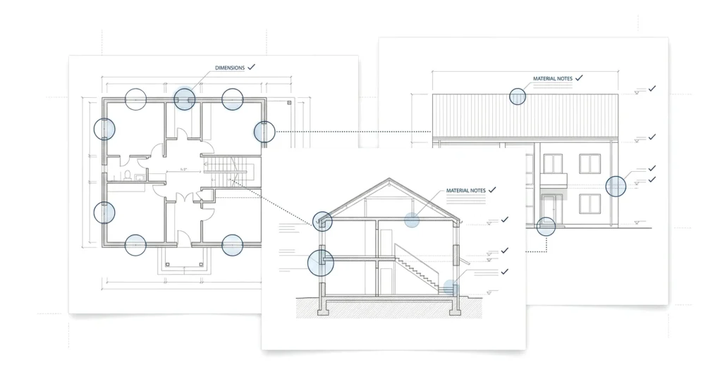
Checklist for reviewing construction drawing details
Before starting construction, every drawing set should be reviewed carefully.
Checklist:
- Verify dimensions and wall thickness
- Confirm building codes compliance
- Check consistency across floor plans, elevations, and section drawings
- Ensure all construction details are included
- Validate materials and notes
This process helps avoid costly mistakes during the building process.
What is a typical roof flashing detail
Roof flashing details protect the building from water intrusion.
A typical flashing detail includes:
- Metal flashing layers
- Waterproof membranes
- Integration with roof and wall systems
These details are critical for maintaining the integrity of the building envelope and ensuring long-term durability.
Hand drafting vs CAD for architectural details
Both manual drafting and CAD are used in architectural drawing details:
- Hand drafting allows quick sketches and supports the creative process
- CAD enables precise dimensions and easy updates
Today, most architects combine both methods to create accurate and efficient drawings.
How to explain architectural details to a homeowner
Explaining architectural drawing details to a homeowner requires simplifying technical drawings.
Focus on:
- Using visual examples and renderings
- Explaining how drawings relate to real life outcomes
- Highlighting key areas like windows, doors, and lighting
This helps clients better understand the design process and feel confident in the project.
If you need help with architectural drawing details or reviewing your project documentation, you can contact the team here:https://mast-team.com/contact/
FAQ
What are architectural drawing details?
They are detailed drawings that show how construction elements are built and connected in a building.
Why are architectural drawings important?
They help communicate design intent and ensure accurate construction.
What is included in construction drawings?
They include floor plans, elevations, section drawings, and detailed construction drawings.
What software is used for architectural drawing details?
AutoCAD, BIM tools, and rendering software are commonly used.
How do architects ensure accuracy in drawings?
By using precise dimensions, consistent symbols, and reviewing the full drawing set.
What is the difference between plan details and section drawings?
Plan details show horizontal views, while section drawings show vertical cuts through the building.